ucsd-et4a
Week 2 - Making Things Move
Agenda
- Review/Discuss HW1 + Reading
- Artist(s) of the Day
- Tutorial: Analog Input and Output
- Analog output
- Analog input
- Analog Read Serial
- Photoresistor Part 1 light sensor
- Tutorial: Making things Move
- Servo sweep
- Servo knob
- Photoresistor Part 2 light responsive motion
- Homework
- Making Things Move (DUE next Wednesday 10/16)
- Assign Project 1 - Biomimicry (DUE Week 4)
Artist(s) of the Day

Daniel Rozin
- Wooden Mirror
- Thousands of servo motors
- Longer video from Wired (2019): https://www.youtube.com/watch?v=kV8v2GKC8WA
- Wooden Mirror (2000) in SIGGRAPH Archives: https://digitalartarchive.siggraph.org/artwork/daniel-rozin-wooden-mirror/
- Danny Rozin portfolio
Analog Input and Output
Analog Output
Commonly called PWM (Pulse Width Modulation).

https://www.arduino.cc/en/Tutorial/BuiltInExamples/Fade
- NOTE: this is a very similar circuit and wiring as Digital Output above.
- the difference is that here we are using
analogWrite()(reference) - and a different pin (one of the PWM capable pins)
- the difference is that here we are using
- Demo:
- Show the “duty cycle” on the oscilloscope.
- Show how a different analog output corresponds to (1) a waveform and (2) a different measured voltage.
- TODO:
- modify the speed at which it fades. (hint: change the
delay(). see the delay reference)
- modify the speed at which it fades. (hint: change the
Analog Input
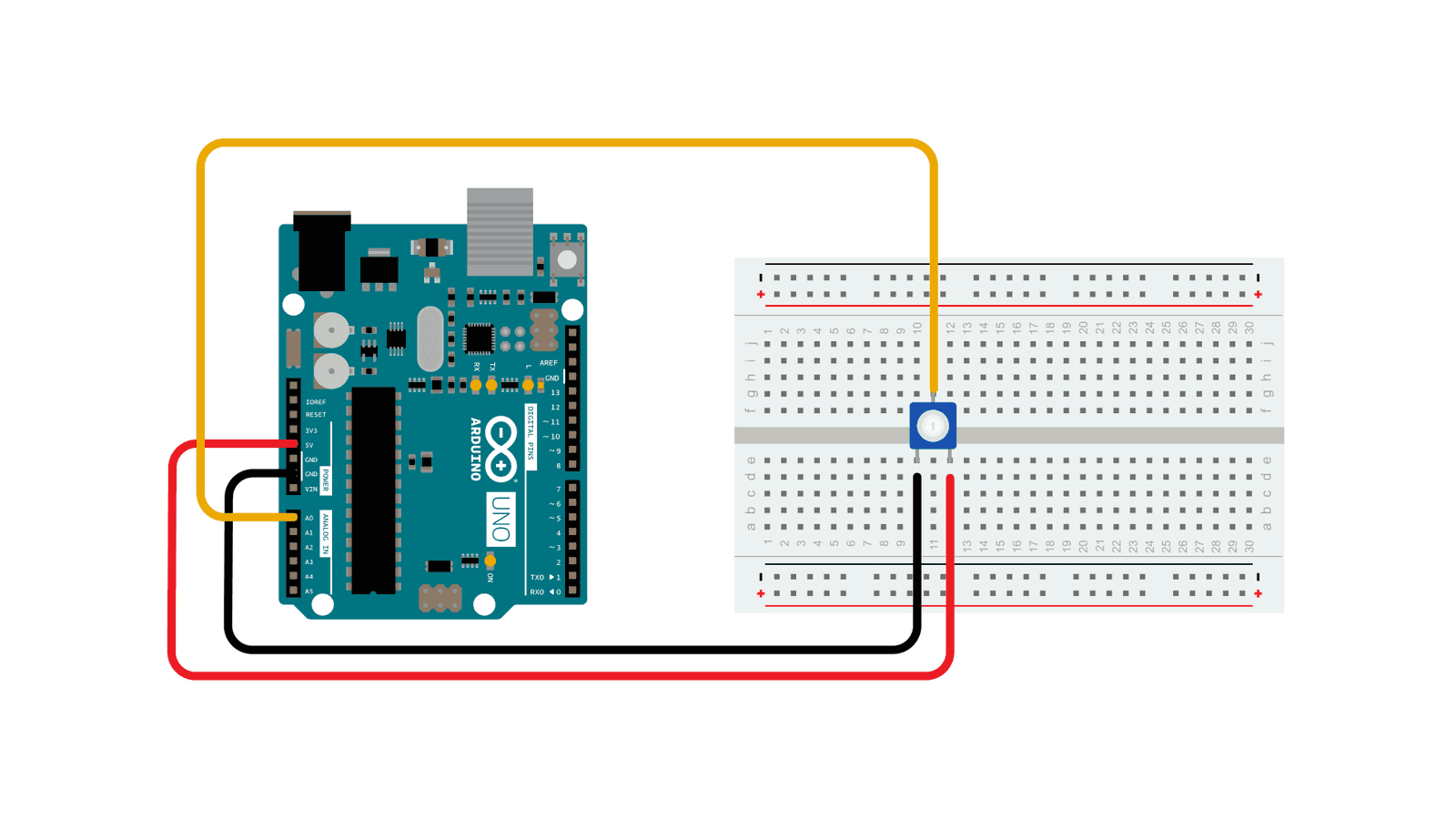
https://www.arduino.cc/en/Tutorial/BuiltInExamples/AnalogInput
- Demo:
- Talk about Voltage, Current, and Resistance (Ohm’s Law)
- Talk about using a multimeter.
- Look at how a potentiometer (as voltage divider) changes voltages
- Show how a changing voltage corresponds to an
analogRead()
Analog Read Serial

https://docs.arduino.cc/built-in-examples/basics/AnalogReadSerial
- Keep the potentiometer hooked up into Analog Input 0 (A0) on the arduino.
- Load the AnalogReadSerial sketch (Examples->01.Basics->AnalogReadSerial) to the arduino.
- Open the serial monitor:

- Look at how moving the potentiometer changes the value of analogRead().
- Activity:
- Use
map()to scale those analog values to 0-255, and use that to fade a jumbo LED (analogWrite())
- Use
- We can use
serial.write()to communicate with p5, or processing, or maxMSP or any other program that can read from a serial port.
Photoresistor Part 1
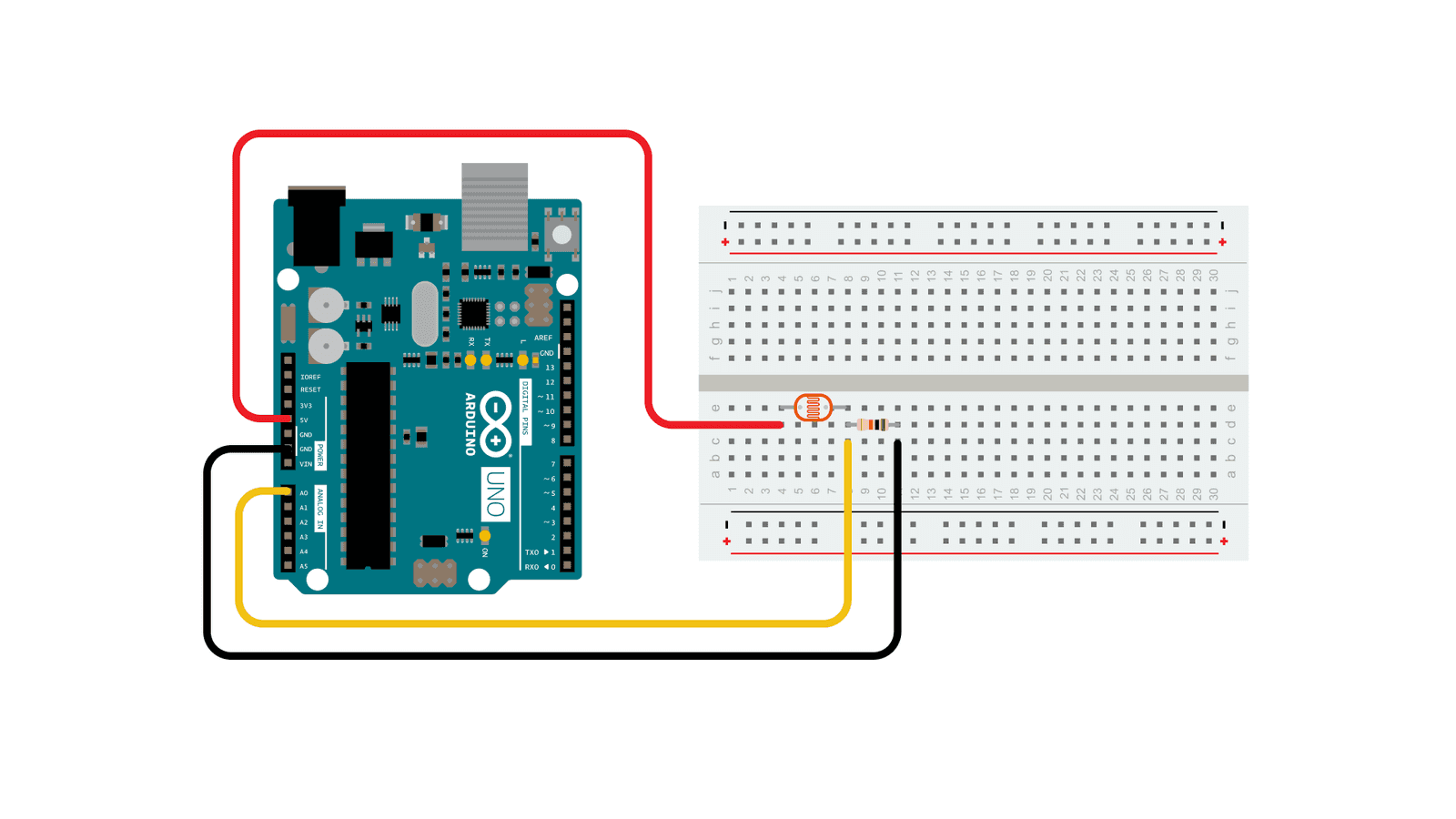
https://www.arduino.cc/en/Tutorial/BuiltInExamples/AnalogInput
- Use a multimeter to see how the resistance changes with the photoresistor.
- (this does not need a circuit. connect the red lead to one side of the photoresister, and the black lead to the other)
- We can put a photoresistor in series with a resistor to make a voltage divider. This is similar to how a potentiometer works. As the resistance of the photoresistor changes (the light changes), the output voltage will change.
- Hook up the circuit in the picture above with a resistor, photoresistor, and wires to ground, 5V, and A0.
- Use AnalogReadSerial from the section above, and use the serial port monitor to see what the range of output voltages is.
- Activity: Use the photoresistor to control the servo from last class, in place of the potentiometer
- Use the serial port to debug the range of analog values coming in from the photo-resistor/resistor voltage divider.
Making Things Move
Another use of Pulse Width Modulation is driving the position of a servo motor.
Servo Sweep
- Install the Servo library:
- Tools -> Manage Libraries:
- Search for Servo. Click Install:
- Select the “Sweep” example:
- Tools -> Manage Libraries:

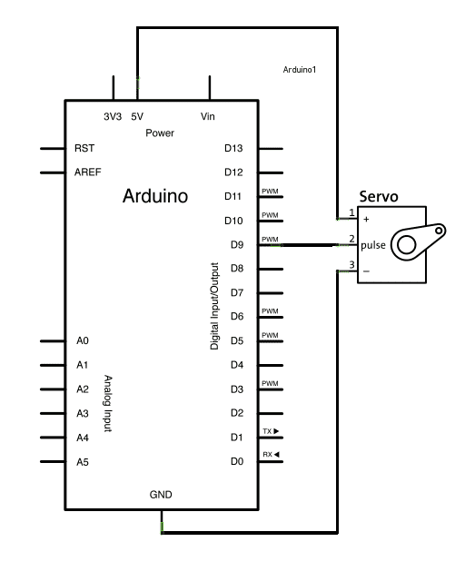
https://www.arduino.cc/en/Tutorial/LibraryExamples/Sweep
- How to read a schematic
- Pulse Width Modulation
- (
analogWrite()!) - more on PWM Secrets of Arduino PWM
- (
Servo Knob
A knob is a kind of simple “sensor” to drive the servo motion.
- Under Examples -> Servo, select the Knob example:
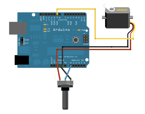
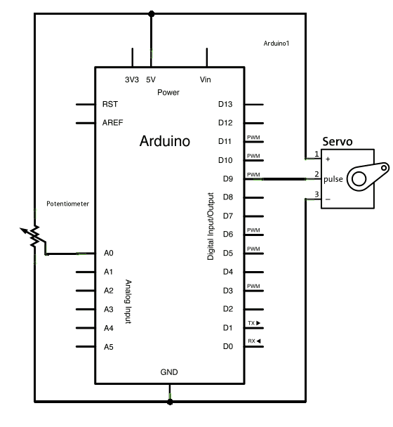
- Reading the schematic.
- Use the servo to control two knobs.
Photoresistor Part 2
With the photoresistor setup and arduino code from part 1 above:
- Use
map()to scale those analog values to 0 -> 180 degrees (the full range of the servo) - Interact with the photoresistor and see the motor move.
- Extension: Instead of directly mapping sensor values to servo position, use the sensor values to trigger specific motions. For instance, have if statements that move it to different positions depending on how much light it sees.
Homework
- Exercise 2: Making Things Move DUE next wednesday 10/16
- Start ideating for Project 1
References
- Sparkfun Tutorial on Pulse Width Modulation


