ucsd-creative-robotics
Week 2 - Making Things Move
Agenda
- Review/Discuss HW1 + Reading
- Artist(s) of the Day
- Tutorial: PWM and Analog Output
- Tutorial: Making things Move
- Servo sweep
- Servo knob
- Photoresistor Part 2 light responsive motion
- Homework
- HW2 Making Things Move (DUE next Tuesday 10/20)
- Project 1 - Augmentation (DUE Week 5)
Artist(s) of the Day

Daniel Rozin
- Wooden Mirror
- Thousands of servo motors
- Longer video from Wired (2019): https://www.youtube.com/watch?v=kV8v2GKC8WA
- Wooden Mirror (2000) in SIGGRAPH Archives: https://digitalartarchive.siggraph.org/artwork/daniel-rozin-wooden-mirror/
- Danny Rozin portfolio
Analog Input and Output
Analog Output
Commonly called PWM (Pulse Width Modulation).
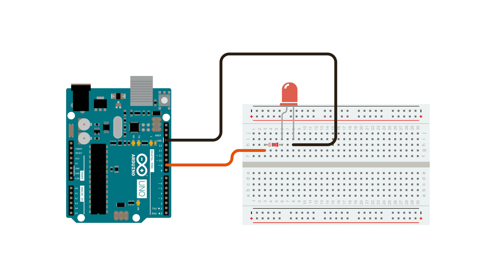
https://www.arduino.cc/en/Tutorial/BuiltInExamples/Fade
- NOTE: this is a very similar circuit and wiring as Digital Output above.
- the difference is that here we are using
analogWrite()(reference) - and a different pin (one of the PWM capable pins)
- the difference is that here we are using
- Demo:
- Show the “duty cycle” on the oscilloscope.
- Show how a different analog output corresponds to (1) a waveform and (2) a different measured voltage.
- TODO:
- modify the speed at which it fades. (hint: change the
delay(). see the delay reference)
- modify the speed at which it fades. (hint: change the
Making Things Move
Another use of Pulse Width Modulation is driving the position of a servo motor.
Servo Sweep
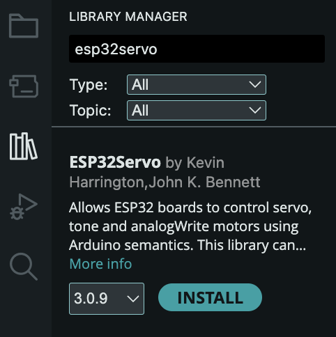
- Install the ESP32Servo library:
- Tools -> Manage Libraries:
- Search for ESP32Servo. Click Install:
- Tools -> Manage Libraries:
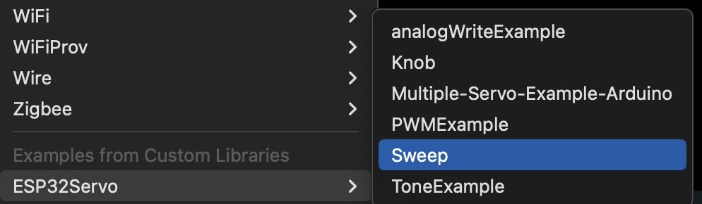
- Under Examples -> ESP32Servo, select the Sweep example:
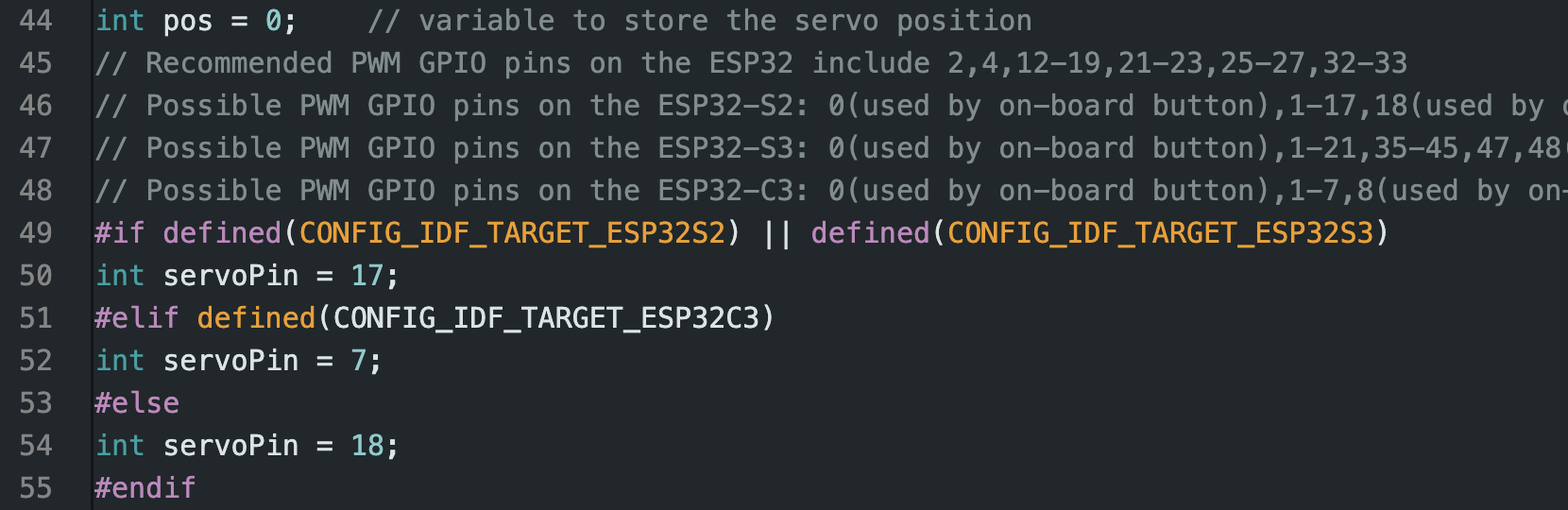
- Make sure that your servo is connected to the pins used in the example code. Or change the pins in the code to match your setup.
- Wire up the servo:
- BLACK/BROWN -> Ground
- RED/YELLOW -> +5V
- ORANGE -> your
servoPin.
- Compile and run the example.

What is PWM?
Timing Diagram

Simplified Wiring Diagram
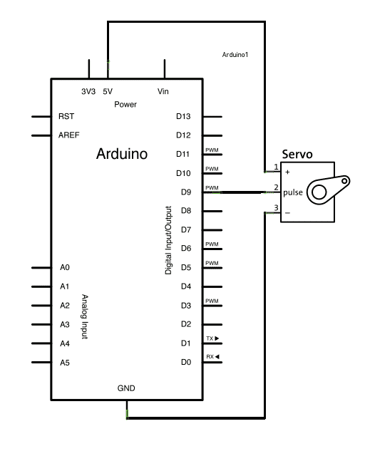
https://www.arduino.cc/en/Tutorial/LibraryExamples/Sweep
Talk Through
- How to read a schematic
- Pulse Width Modulation
- (
analogWrite()!) - more on PWM Secrets of Arduino PWM
- (
Servo Knob
We are going to use the potentiometer knob as an input device. You can think of a knob as a kind of simple “sensor” to drive the servo motion.
- Under Examples -> ESP32Servo, select the Knob example:

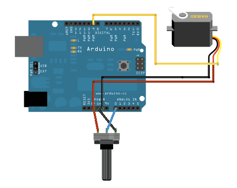
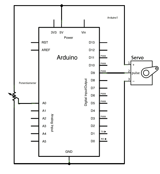
- Reading the schematic.
- Use the knob to control the servo.
Homework
- Exercise 2: Making Things Move DUE next Tuesday 1/20
- Start ideating for Project 1 Augmentation
References
- Sparkfun Tutorial on Pulse Width Modulation